How Do Humbuckers Work?
We all know the sound – that pesky buzz that can ruin a perfect take in the studio, or distract your audience when playing live. We’re talking about 50-60 Cycle […]


3-Way, 4-Way, 5-Way, Toggle, Blade, Rotary – There’s a lot of switches available for your electric guitar. Some come in a variety of designs and can introduce some new functionality to your guitar. These little connectors are powerful when you know how to use them, so let’s learn how they work!
Today, we’re going to talk about Blade Switches. Blade Switches are the most common variety of switch, used a lot on Stratocasters and Telecasters, primarily. With understanding the Blade Switch, you can customize how your electric guitar’s pickups behave and sound; making your guitar even more unique than it is. Let’s dive in!
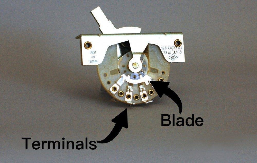
The most important thing to note about the switch is that it’s a connector. Depending on how you have it wired, its’ sole purpose is to send your signal somewhere. It does this by using the Blade to wipe across the Terminals. When the blade connects to the terminal, the signals join through to the path you’ve designed.
See below to see how the terminals are laid out: There are two sides of the switch, Side A, and Side B. These sides are entirely independent of each other, meaning A1 can’t be connected to B0 unless a jumper is activating both sides of the switch (more on this later).
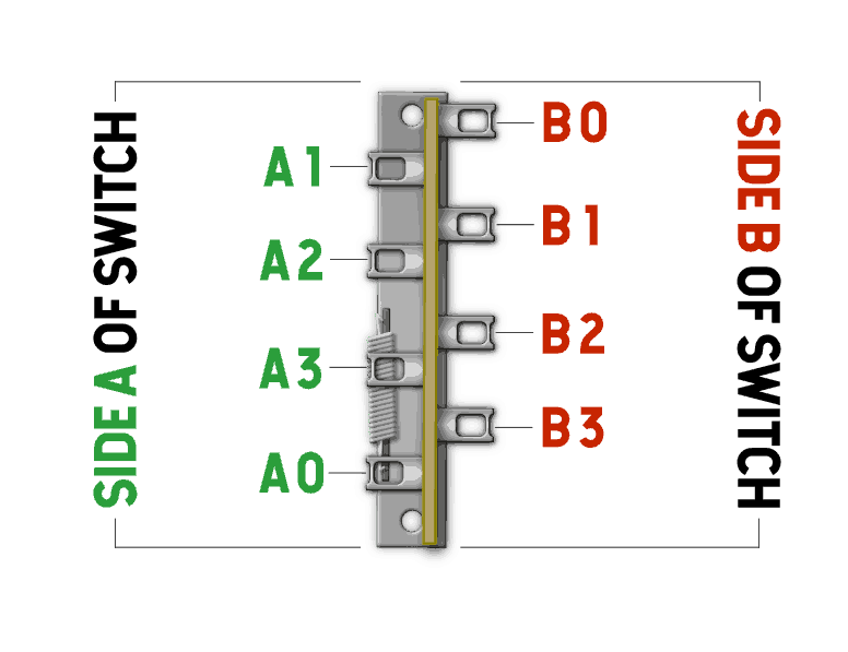
You can see that the switch has 2 Sides, and 4 Terminals Per Side. 1-3 are the selectable terminals, and the 0 is your common – it’s always connected. As we mentioned earlier, the sole purpose of the switch is a connector. Depending on what type of switch you have, all that is happening is the blade connecting Lugs 1-3 to Lug 0.
For example, if you had a neck pickup wired up to A3, when you select the Neck position on your switch, A3 is being connected to A0. If you wired A0 to your volume pot for output, that’s how the switch would connect your Neck pickup through the output.
5-Way blade switching is the most uncomplicated blade switch to comprehend, which is why we’re going to start here. The Blades can choose two terminals at the same time on the same side. The 5-Way Blade Switch looks a lot like the 3-Way Blade, except it has a slightly larger wiper blade to choose more than one terminal at the same time. This enlarged blade is useful for selecting the Bridge and Middle pickup at the same time, to get that infamous “quack” tone.
The image below shows what terminals are connected when you’re in each position. Please note that the “0” terminals are your common connections – they are always connected.

On Position 1 (Bridge), A1 and A0 connect, and B0 and B1 connect.
On Position 2 (Bridge and Middle) A1, A2, and A0 are connected, and B1, B2, and B0 connect, and so forth.
I’m sure you can see a pattern emerging here. Let’s show you a real-world example on how we wire this up:
There are many ways to wire up a Stratocaster; however, let’s take a look at a traditional one. Please note that we’ve added a jumper here! The purpose of this jumper activates (or connects) the second side of the switch. So, we have an input side of the switch where our pickups solder to, and an output side of the switch where our signal is going.
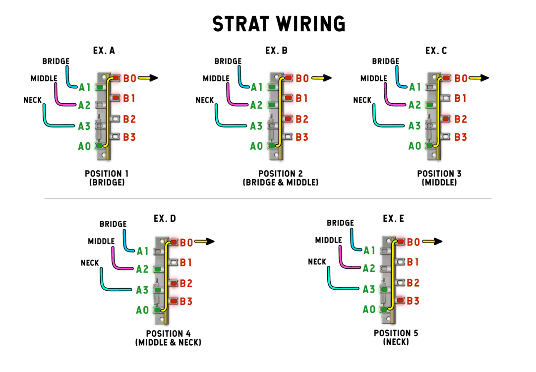
As you can see, all the pickups are entering the switch from Side A. Technically; you can use A0 as your output to the volume pot, but, you can have a lot more functionality by adding a jumper from A0 to B0!
Connecting both sides of the switch allows Side B to become an output section. So, if you have two tone controls, you can wire up the Bridge to one Tone Control and the Neck and the middle to another. You have a lot more versatility with using both sides of the switch in this way.
Before we get into additional switching, let’s talk about the other side of the switch:
By activating the Side B (or the Side A, depending on how you’re wiring this up), you can achieve some more versatility with this switch. To activate the other side, you run a jumper from one side of the switch to the other side. Doing this lets electricity move to the second side, allowing a lot more tonal combinations and output configurations. To get your signal to both sides, we run a jumper from one Common to the other Common. Let’s take a look at what we can do: As you can see
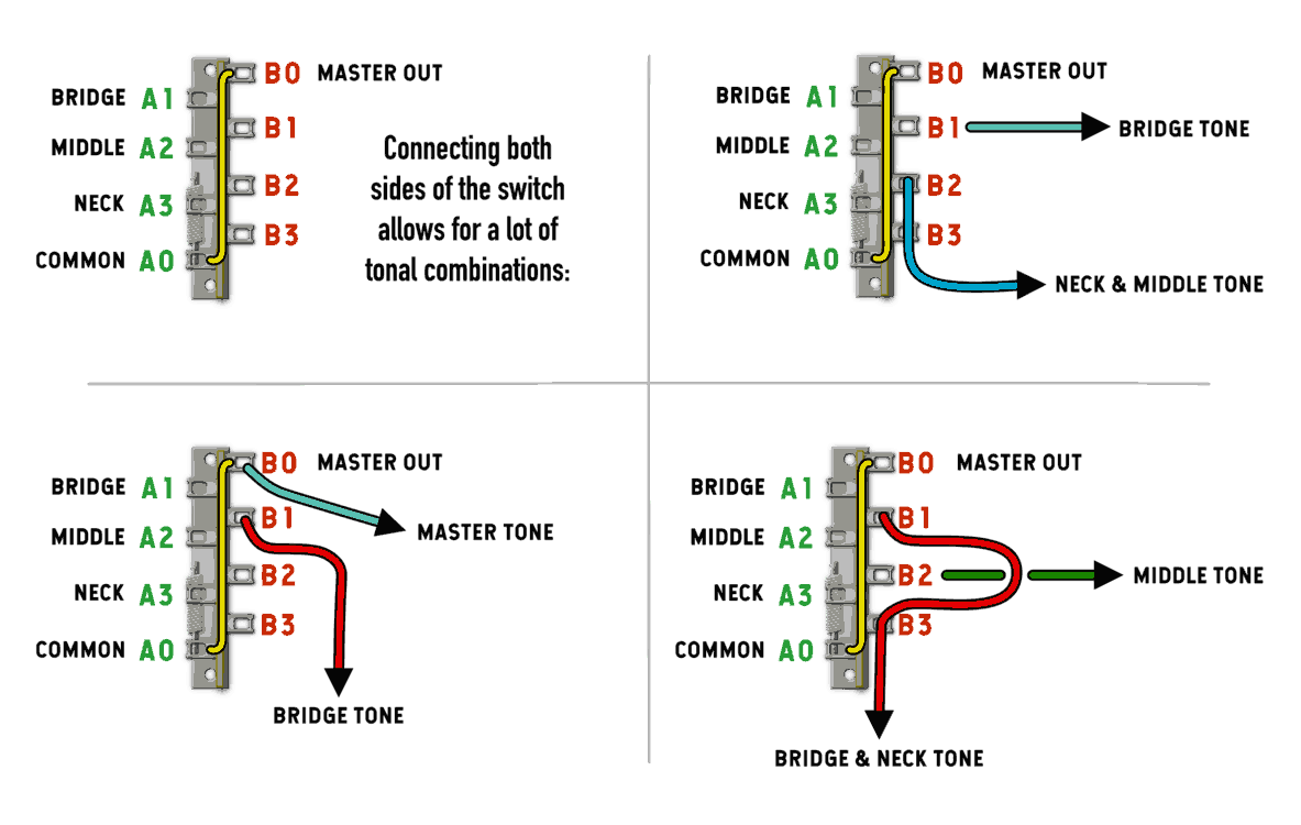
As you can see, by jumping to the next side of the switch, you can create a lot of tonal variations with your Strat. Having this second side of the switch is really useful when you have two tone controls – you can use the Neck and Middle on one tone control, and the Bridge on a separate tone control with a different value. Now that we’ve understood the basics a bit and talked about some real Stratocaster examples, let’s get into 3-Way Switching:
The 3-Way Blade switch is one of the original switches for the guitar. It was introduced on the original 1950’s Broadcasters with two pickups and solidified with the Telecaster in 1951. The 3-Way Switch, like the 5-Way Switch, is comprised of 2 sides, with 4 terminals on each side. The only difference here is the size of the blade that wipes the terminals. The 3 Way Blade only connects one terminal at a time, where the 5-Way blade switch can connect two terminals at a time.
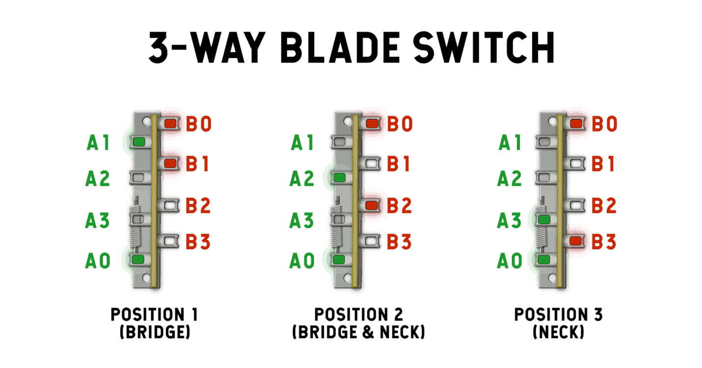
This should look familiar! The “0”‘s are always connected, and the blade selects one terminal at a time. So, even though this seems easier, there are a few challenges presented when using 2 pickups – let’s take a look:
There’s a challenge when using a 3-Way switch with a 2 pickup guitar: the blades only choose one terminal at a time. 5-Way switches don’t have this problem. We can easily remedy this with a little bit of jumper Kung-Fu. There’s a lot of 3-way switch diagrams that are confusing and difficult to understand. Our favorite is much more understandable. See below for an illustration!
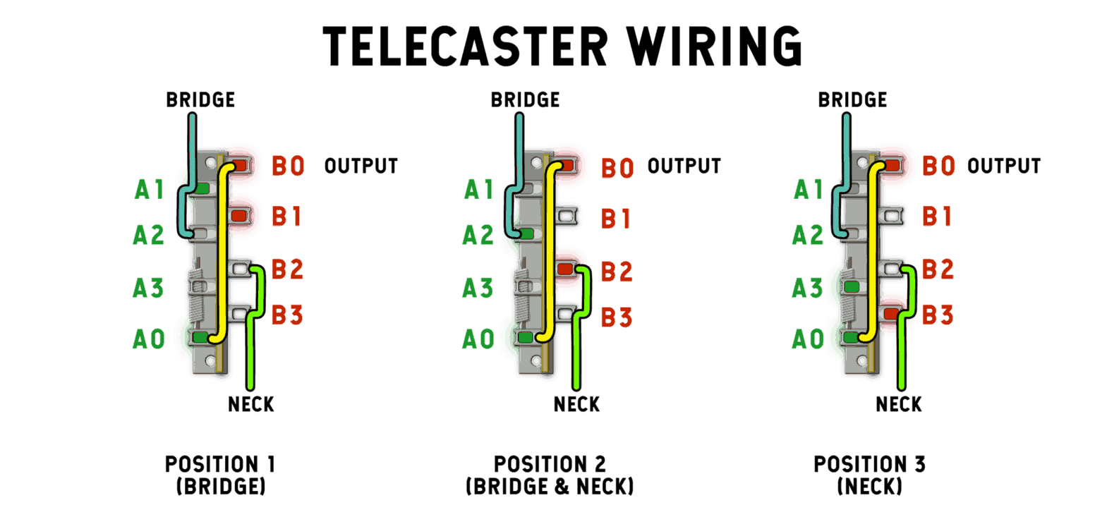
With this wiring, we wire the Bridge into both A1 and A2. We wire the Neck to both B2 and B3. We also create a Jumper from A0 to B0. B0 is our Master Output.
Position 1 (Bridge): Terminals A1 and B1 are selected. Nothing is wired up to B1, but the Bridge is wired up to A1, which is connected to A0, which is jumped to B0 Output.
Position 2: (Neck and Bridge): A2 and B2 are both selected. B2 is connected to B0, which is Output.
Position 3: (Neck Only): A3 and B3 are selected. Nothing is wired up to A3, but the Neck is wired up to B3, which is connected to B0 – Output.
Oh yeah – we’ll need a breather after that one. There are lots of ways to wire the switch up, and you can experiment with other and new creative ways to re-route your pickups signals. We hope that this article has been comprehensive as well as easy to understand! Until next time, Cheers!
39 Comments For This Post
Want to chime in to the conversation? Please do so! Please respect others.
Hi Tyler, is there a way to wire a 3-way switch to an On-Off-On configuration? Instead of blending the signals in the center position, I need to pull both signals to ground in center position. If not, could a 5-way switch be configured that way?
Hey Dan, Yes. Instead of bridging the pickups’ wires on both sides of the switch (A1 → A2 for the Neck & B2 → B3 for the Bridge), simply wire your pickups only to A1 and B3. That way, in the middle position, your switch is connected to nothing, therefore the guitar should be silent. That said, you might need to run a ground jumper on A2 → B3 → Ground in order to keep any extra noise down, but I believe this should be simple to achieve.
Dear Sir, I’m not a super technician, but I am trying to rebuild a Vox phantom guitar. I’ve completed most parts, but I’m stuck with the electrics. It’s like a Strat and has three single coil pickups, with two tones and one volume.
The pickup selection is by a 5way rotary switch. I cannot find a diagram at all. Do you keep those switches? And if so, the wiring diagram.
Hey Phil, we do not have any 5-Way rotary switches available. This may help.
How to wire a 3 position switch for normal output , blower(straight to jack), and kill. I have a double stacked volume pot with one output and two p90 in and grounds. One tone. One 3 way. Since the volumes bypass the switch it just hangs there looking pretty. I thought i could use it as a normal,blower,kill switch but don’t know how
Two questions. What is considered the #1 position on a tele selector switch. Is it for the neck or bridge pickup. I don’t know if it is individual preference or not. My second question can a tele with a strat middle pickup be wired so that you can get the middle pickup to operate separately from the neck and bridge pickup. My example is position 1 is the neck pickup, position 2 is the middle pickup only, position 3 is the neck and bridge pickup only, 4 position is bridge pickup only. The 2nd and 3rd position can be interchanged if needed to make this work. If this cannot work can a 5 way start switch do the job? Thanks.
Hey Mel,
I believe it’s personal preference, but I and most people at the shop call position 1 the Bridge. I haven’t seen a diagram like that, but I’m sure it’s possible. I would check some forums for more specific help regarding that – we don’t supply custom diagrams.
Hey Tyler,
What I really need at this point, as my semi-hollow TL lies waiting for me, is to know how I’d wire 3 pickups to a 3-way, BUT independently.
So as, for example, pos. 1 = bridge, pos. 2 = middle, pos. 3 = neck.
Thanks!
Much appreciated for a.s.a.p.
If a switch is wired so as to short the “top” coil of a humbucker and derive a signal from the center tap, and in another position it derives a signal from the same center tap but leaves the hot side of the “top” coil unconnected, is does this “top” coil impart an interference or distortion on the “bottom” coil that’s being used as a single coil?
I’m confused, not by the article, the article was great and I appreciate it so much. But I just read through the whole thing and there is no section on 4 way switches. It goes from a basic overview of all switches, to explaining the 5 way, then the 3 way and then it’s over. But I’m the comments people keep remarking on th section that discusses the 4 way. I’m confused and frankly I need the info on the 4 way more than the other two. Thanks.
Thanks so much for putting this up. I struggled for a long time before I found this article. I’m running a Pacifica with a three way and two P90s, the neck pup is a Fralin pup I bought a while back. Yours was by far the easiest wiring diagram to follow of many, and things turned out great. As a bonus the middle position is hum canceling! As an added bonus there’s a drop in gain so that I can use it for clean passages and jump to distorted by going to neck or bridge. Some folks may not want that, but for me it’s very convenient.
Hi. This article is quite helpful, but I noticed a few errors in the diagrams (both sides being labeled A0 – A3, instead of one side as A and the other as B). The erroneous images are the one labeled “Five way blade switch” and “Strat wiring.”
Also, in the “Position 3” bit for “How [a 3-way switch] Works” you said: “A3 and A3 are selected … ” The second “A3” should be “B3.”
Hello Tyler. I love your articles and wiring diagrams. I’m curious about this one though. In your explanation of how the 4 way works, for instance, you say in position 1 that the neck black lead is connected to A1, but the image shows it as being connected to A0. The discrepancies seem to continue in the same manner for some of the following explanations. So, my questions is, which ones are correct? The explanations, or the diagrams/images? Thank you.
Brian
Hey Brian,
Thanks for catching that. I will edit for clarity! New diagrams are coming for this piece soon.
Cheers.
Tyler
Very nice! I would have liked to have seen some different methods of wiring a tapped pup into the blade switch. I’m interested in seeing other methods.
I, finally, think I get it. Thanks!
Now, enlighten me further with a similarly detailed explanation of the Rotary Switch.
It would be a great addition to this group of topics.
Thanks!
Thanks, Dave.
Rotary switches might be a part 2… I don’t have it planned as of yet, but I’ll put it on the list.
Tyler
Excellent article. Finally someone explains it properly.
Great article. I’ve used similar wiring for all my Strat and Tele work. Recently I tried to install a Japanese made DM-50 5-way switch following the same wiring. However, for some reason it isn’t working. Ever worked with DM-50 switches? Is the wiring different?
Thanks for the great article!
Thanks, Nate.
It could be that the “common” is on the opposite end of each side of the switch as the CRL switch depicted in the examples above. For example, the CRL switches’ terminals are listed A1, A2, A3, A0 (Common). Your switch might be A0, A1, A2, A3. This would change the wiring, for sure. Take a look at the operation and see which terminal is connected all the time.
Hope this helps,
T
I like the versatility that the four way switch allows. If I had a bridge and neck single coil pickup with a five way switch, is it possible to get this configuration:
1. Bridge
2. Bridge and Neck parallel
3. Bridge and neck Series
4. Bridge and Neck out of phase
5. Neck
I get it until the 4way switch. You said “B1(Bridge White” since the first explanation of how it works while in the picture, B1 is Neck White instead. I got lost since then.
Aryo,
We get it – it’s a confusing topic. Check out this article here to clarify.
I have a 1995 G&L ASAT which needs a new pickup switch. Readings about the 4-way option I’m intrigued if this will give the bridge pick a more rounded/beefier tone, without affective the others, as sometimes it (the bridge pickup) can be a bit on the bright side, but hey, its a Tele. Don’t get me wrong, I like this tone, but to have another by using a 4-way in lieu of the 3-way seems like it might be a nice modification to add to the already wonderful sounds this Tele produces, which I wouldn’t want to change just for the sake of having an alternate (beefier) Bridge tone.
Brian,
This is a good question, and I’m going with my gut and saying the answer is no. The 4-Way switch won’t affect the tone of the bridge pickup unless you’re on the Series selection. Then, it will sound like a giant humbucker. It’s a pretty drastic difference. The the most efficient way to do what you’re asking is to opt for an overwound, beefier-sounding bridge pickup by itself. Putting your pickups in series will make it sound thicker, but you’re essentially doubling your volume and thickness at the same time. It’s drastic. I hope this helps.
T
What a great article.
Finally I get it.
I can see what Doug in VA is saying , but… the diagrams are very helpful. I might just be modding my tele with this info !
I’ve wired up 4-way for Tele a long while and Strat switches to have the forward tone control affect the bridge pickup as well as the neck pickup. But the article is complicated enough to confuse and frustrate most ordinary guys like me. It’s useful as a reference and for guitar geeks, but regular guys will glaze over. Too much too quick.
Doug,
Thanks for your feedback!
Tyler