All of our humbuckers are wired in series, which means one coil’s output goes into another’s input. This explains why all humbuckers sound big, bold, and beefy. But, what if you wanted to make your humbuckers sound more like a strat? Well, here’s May’s Mod of The Month: Series / Parallel Switching
WHAT’S THE DIFFERENCE BETWEEN PARALLEL AND SERIES?
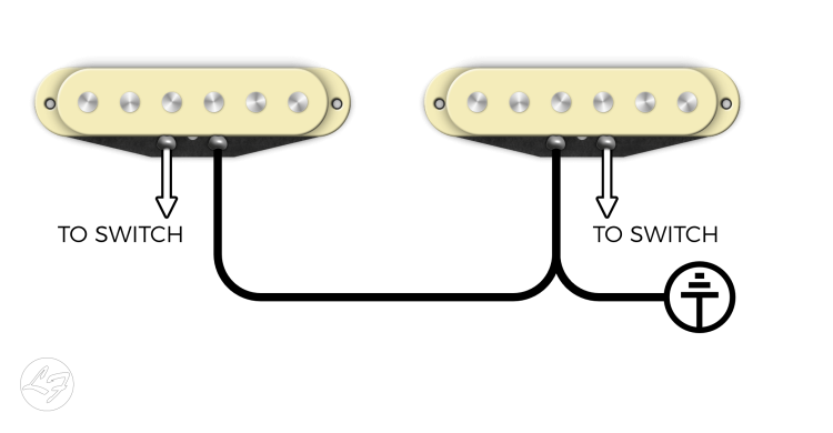
In a standard guitar, like a Strat or a Tele, your pickups are wired in Parallel. What this means is each pickup has its own path of output. For instance, the White (hot) leads are attached to the switch, and the Black leads are attached to Ground. Series wiring puts your pickup’s outputs into your other pickups. To illustrate, we’ve literally made an illustration:
Parallel Wiring
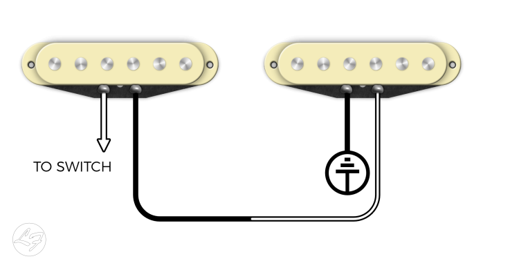
Parallel wiring gives the pickup signal the shortest possible distance to the Output Jack. Series wiring gives the signal a much greater distance to travel. Having to travel a greater distance, the signal experiences more resistance, thus getting bigger and beefier.
Series Wiring
Let’s look at our Humbucker wiring: you have a Slug Coil (the coil with Alnico magnets), and the Screw Coil (the coil with adjustable screws).
Black is the start of the Slug Coil (Ground) Redis the finish of the Slug Coil Greenis the finish of the Screw Coil White is the start of the Screw Coil (Output)
Our Humbuckers have the following signal path: Black>Red>Green > White. This is our standard series wiring. Wiring the pickups in Parallel, Black > Green >Red >White. The “Starts” of the coils are wired together, and the “Finishes” of each coil are wound together.
The color codes shown are for our humbuckers. Other manufacturers have different color codes.
By replacing your volume pot with a 500K Push/Pull, you can achieve Series / Parallel with the pull of the pot. When Pushed Down, your humbucker is working usually – in series. When pulled up, your Humbucker is wired in Parallel. Remember that the Shield is always grounded (not depicted in the drawing below).
How It Works:
Red is connected to Green in terminals B & C- like a standard humbucker when pushed down. White and Black are not connected to anything, leaving them out of the switch. When pulled up, Red connects to white (B – A), and Green connects to Black (E-D). This gives you the Parallel “Strat” tone we’ve all come to love.
👋 I'm Tyler Delsack, the Manager of Fralin Pickups.
I've been a guitarist for 28 years, and along with managing the shop and working on this Website, I love tinkering with things!
The BEGINNING: Lindy Fralin Pickups was started from a pickup repair and rewind business. It’s how Lindy started building pickups, and how he started designing new models. It’s the cornerstone of […]
Practicing your guitar makes you a better guitar player. Understanding guitar wiring makes you a better Tone Wizard. And, properly grounding your guitar’s electronics makes your guitar as quiet as […]
D.C. Resistance, or a pickup’s Ohm reading, is not the “Holy Grail” of understanding a pickup’s output – it will give you a rough understanding. On occasion, we get a […]
Something must have changed between the May 18 2017 post of this article and the Nov 4 2024 revision. This almost reads like it was run through Claude. Your graphic has a solder blob on, what I think you’re calling, ‘pin E’ with no wire connected (should be the black wire from the humbucker).
The way you’re referencing up and down is also confusing since our drawing is a side view of the pot with the string-side of the guitar to the bottom of the drawing and the buckle-rash side of the guitar towards the top of the drawing.
It would be a better idea to use ‘pull out’ and ‘push in’ to talk about the 2p2t switch position. Since ‘pulling up’ on the push-pull pot would be extending the knob towards the bottom of the drawing, and ‘pushing down’ would be pressing the knob towards the top of the drawing.
For each of the poles (red columns in the diagram) pulled out, the middle pin and the pin towards the string-side of the guitar are joined. Pushed in, the middle pin and the pin towards the ‘back’ of the guitar are joined.
The pins would be labeled like this.
F C
E B
D A
The site’s a wonderful resource for guitar electronics. This one needs a little polish before it’s of the same standard as most of the other posts.
This diagram would be much more useful if the letters you use to identify the terminals – A, B, C, D, E – were actually on the diagram.
Also, you have the white (signal from pickup) going direct to the end of the pot and then the wiper of that pot going direct to the jack. So that pickup’s output is always on unless you ground the lime green wire via the switch, killing all output from the guitar.
I’d guess that the white wire should go to TO SWITCH and you were suggesting a one-volume control guitar, but with only half a diagram here, it’s impossible to tell what the intent is.
Good job – thanks.
I’m a experimenter and have learned a lot about what sounds good and what works on stage simply by trial and error. Go for it with a test guitar and study the various wiring diagrams until you can imagine them and almost hear what works. My favorite coil tap is using the spare leg of the tone control for each humbucking. Adding a phase switch, you can choose which coil to tap.
Series parallel works for me though because the ‘strat’ sound remains humbucking.
Also, try grounding a coil through various capacitors for a beefier parrallel sound.
Experiment! It’s fun!
I have a squier Jaguar vintage modified HH, which I am experimenting with different mods for. So I have two Seymour Duncan hot rodded humbuckers, a total of four 2 position/6 pin slide toggle switches, two 250k tone pots (one for each pup), and two 500k CTS push/pull volume pots (one for each pup). I am planning on using the switch function of the volume pots to coil split each pup. I am also planning on using 2 of the 4 toggles as kill switches for each pup. That leaves me with 2 toggles to use as mods. Would I want to place the toggle mod switches in parallel with the coil splits, or in series with the coil splits, and if I should do the latter, should the mod toggles be placed before the kill switches, before the coil splits, before both, or before neither. Any info is appreciated.
Is it possible to wire a rotary switch to do this mod with a three hum bucker guitar? IE-An SG with a six position switch master volume and tone and rotary switch with positions for normal mode all pickups, positions 2-4 each individual pup and position 5 all pups parallel?
Thank you!
Are you talking about simple switching? If you have a 3 Way Toggle switch, the middle position puts both pickups in Parallel. This mod puts the humbucker itself into parallel.
I have a Suhr Andy Wood Sig Modern T HH with Series Parallel. So, essentially, when in series (pushed down) it’s more like a Les Paul and pulled up is more like a Strat effect? It’s seems like a different way to get a similar effect cause by coil splitting, if I’m understanding this correctly?
I have a PJ Bass and need to make the neck P bass PU sound more like a single Jazz. Will a push-pull pot mod and this Parallel set up work? Would this pretty much be the exact directions to be able to switch the P Bass PUs in and out of “stock” to “parallel” (less boomy) mode? Thanks!
Currently, the hot(s) from my pickups go to the 3 way toggle first. In this diagram they would go to the dpdt first, then the 3 way toggle? At that point, would the 3 way go to the output jack of the guitar?
If you want this option for both pickups, you have to wire both to the same dpdt switch?
They would need to go to the DPDT switch before going to the 3-Way Toggle. If you have two pickups and want to perform this mod on both pickups, you’d need each pickup going to it’s own independent switch before the 3-Way Toggle. From the Toggle, you’ll go to the output jack.
If I have an HSS strat, can this be accomplished by wiring the tone pot that is connected to the Humbucker rather than wiring the volume pot? I adjusted the switch so that the 2 single coils have a tone control, and the humbucker has a separate tone control.


Something must have changed between the May 18 2017 post of this article and the Nov 4 2024 revision. This almost reads like it was run through Claude. Your graphic has a solder blob on, what I think you’re calling, ‘pin E’ with no wire connected (should be the black wire from the humbucker).
The way you’re referencing up and down is also confusing since our drawing is a side view of the pot with the string-side of the guitar to the bottom of the drawing and the buckle-rash side of the guitar towards the top of the drawing.
It would be a better idea to use ‘pull out’ and ‘push in’ to talk about the 2p2t switch position. Since ‘pulling up’ on the push-pull pot would be extending the knob towards the bottom of the drawing, and ‘pushing down’ would be pressing the knob towards the top of the drawing.
For each of the poles (red columns in the diagram) pulled out, the middle pin and the pin towards the string-side of the guitar are joined. Pushed in, the middle pin and the pin towards the ‘back’ of the guitar are joined.
The pins would be labeled like this.
F C
E B
D A
The site’s a wonderful resource for guitar electronics. This one needs a little polish before it’s of the same standard as most of the other posts.
This diagram would be much more useful if the letters you use to identify the terminals – A, B, C, D, E – were actually on the diagram.
Also, you have the white (signal from pickup) going direct to the end of the pot and then the wiper of that pot going direct to the jack. So that pickup’s output is always on unless you ground the lime green wire via the switch, killing all output from the guitar.
I’d guess that the white wire should go to TO SWITCH and you were suggesting a one-volume control guitar, but with only half a diagram here, it’s impossible to tell what the intent is.
73 strat u .s .a wiring sound diagram l
Good job – thanks.
I’m a experimenter and have learned a lot about what sounds good and what works on stage simply by trial and error. Go for it with a test guitar and study the various wiring diagrams until you can imagine them and almost hear what works. My favorite coil tap is using the spare leg of the tone control for each humbucking. Adding a phase switch, you can choose which coil to tap.
Series parallel works for me though because the ‘strat’ sound remains humbucking.
Also, try grounding a coil through various capacitors for a beefier parrallel sound.
Experiment! It’s fun!
I have a squier Jaguar vintage modified HH, which I am experimenting with different mods for. So I have two Seymour Duncan hot rodded humbuckers, a total of four 2 position/6 pin slide toggle switches, two 250k tone pots (one for each pup), and two 500k CTS push/pull volume pots (one for each pup). I am planning on using the switch function of the volume pots to coil split each pup. I am also planning on using 2 of the 4 toggles as kill switches for each pup. That leaves me with 2 toggles to use as mods. Would I want to place the toggle mod switches in parallel with the coil splits, or in series with the coil splits, and if I should do the latter, should the mod toggles be placed before the kill switches, before the coil splits, before both, or before neither. Any info is appreciated.
Is it possible to wire a rotary switch to do this mod with a three hum bucker guitar? IE-An SG with a six position switch master volume and tone and rotary switch with positions for normal mode all pickups, positions 2-4 each individual pup and position 5 all pups parallel?
Thank you!
Is it possible to do this mod with single dpdt that puts both neck and bridge in parallel?
Hey Dan,
Are you talking about simple switching? If you have a 3 Way Toggle switch, the middle position puts both pickups in Parallel. This mod puts the humbucker itself into parallel.
I have a Suhr Andy Wood Sig Modern T HH with Series Parallel. So, essentially, when in series (pushed down) it’s more like a Les Paul and pulled up is more like a Strat effect? It’s seems like a different way to get a similar effect cause by coil splitting, if I’m understanding this correctly?
What pot should we use when having a humbucker in parallel mode: 250k or 500k?
500K is recommended.
I have a PJ Bass and need to make the neck P bass PU sound more like a single Jazz. Will a push-pull pot mod and this Parallel set up work? Would this pretty much be the exact directions to be able to switch the P Bass PUs in and out of “stock” to “parallel” (less boomy) mode? Thanks!
Currently, the hot(s) from my pickups go to the 3 way toggle first. In this diagram they would go to the dpdt first, then the 3 way toggle? At that point, would the 3 way go to the output jack of the guitar?
If you want this option for both pickups, you have to wire both to the same dpdt switch?
Jason,
They would need to go to the DPDT switch before going to the 3-Way Toggle. If you have two pickups and want to perform this mod on both pickups, you’d need each pickup going to it’s own independent switch before the 3-Way Toggle. From the Toggle, you’ll go to the output jack.
Tyler
If I have an HSS strat, can this be accomplished by wiring the tone pot that is connected to the Humbucker rather than wiring the volume pot? I adjusted the switch so that the 2 single coils have a tone control, and the humbucker has a separate tone control.
Paul,
Sure thing. Follow the diagrams under the “Second Side Of The Switch” part of this article here.
Tyler