How Do Tone Capacitors Work?
The Tone Cap is an incredibly useful tone-shaping tool. Understanding the basics will help you choose the right tone cap for your style. There are a ton of variations of […]


We get asked about 4-way Switching a lot. It’s a simple mod that puts your pickups in Series instead of Parallel on your Telecaster. Using the 4-way switching modification, you can get a unique, beefy tone with both pickups, adding a new dimension to your favorite guitar.
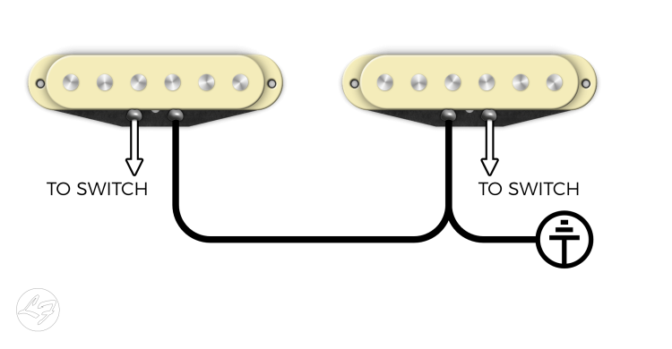
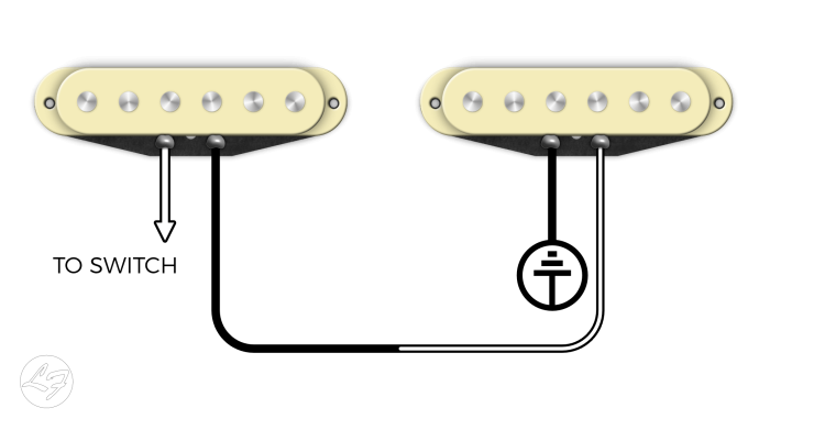
Most guitar wiring configurations feature parallel wiring. It’s the standard operation of a Stratocaster or Telecaster, yielding the famous “quack” tone that is so well known. Parallel wiring features individual outputs for pickups – each pickup has its path to the output. For instance, the White (hot) leads connect to the switch, and the Black leads attach to Ground. It provides the shortest possible distance to the output jack.

You might have noticed a volume drop when you switch between pickups in the middle positions. With parallel wiring, the perceived sound decreases when combined with another pickup.
For instance, if you only selected your Bridge pickup, it’s output is 100%. When combined with another pickup, say, the Middle pickup, it’s output seems to drop by approximately 25%. The combination of the Bridge and Middle might result in a total combined output of, say, 50%.

In series wiring, the output of one pickup connects to the input of the next. This connection means the current flows through each pickup in sequence, from one to the next, before it reaches the output. Series wiring gives the signal a much longer distance to travel, resulting in a beefier tone with increased output. When wiring your pickups in series, the combined signals would equate to roughly 200% or twice the output.
With a 4 Way Switch, you get the following switching capabilities:

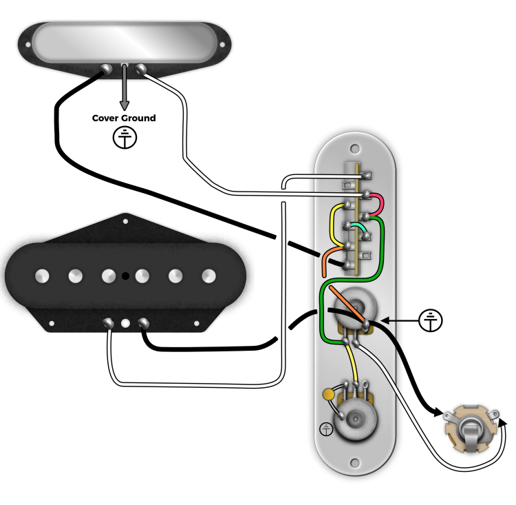
To wire it up, take a look at the following diagram:
Note: If your Neck Pickup has a cover, you will need to separate the jumper connecting the cover to ground and run a separate wire off of the cover to be grounded separately. For a How-To, check out our guide here.
Neck White = Connected To Output
Neck Black = Connected to Nothing*
*(Since this is the coil wire, the Neck pickup doesn’t have continuity)
Bridge White = Connected to Output
Bridge Black = Hard Ground to Pot
Neck White = Connected To Output
Neck Black = Ground
Bridge White = Connected To Output
Bridge Black = Hard Ground To Pot
Neck White = Connected To Output
Neck Black = Bridge White
Bridge White = Neck Black
Bridge Black = Hard Ground To Pot
Neck White = Connected To Output
Neck Black = Ground
Bridge White = Connected To Nothing
Bridge Black = Hard Ground To Pot
If you know this is the mod you would like to do, you can order our pickups with a “3-Wire Neck“. What we will do is give you a lead that runs off of the cover. If you already have a Tele Neck and want to convert to a 4-Way Switch, you will need to solder a wire to your cover and remove the ground connection from your coil. Basically, clip the jumper wire that grounds your cover to your black lead. To see how this mod is performed, check out our guide here: Convert your Tele Neck into a 3-Wire Neck
We hope you found this article helpful! Give us a call or shoot us an email with any questions.
95 Comments For This Post
Want to chime in to the conversation? Please do so! Please respect others.
How would I use a 4-way switch, if the guitar has a humbucker at the bridge and a singlecoil at the neck?
With a standard switch, I get
a) bridge HB (both coils in series)
b) neck SC and one coil of the HB in parallel, the other coil is shortened
c) neck SC
…and all of these sounds are useful, I don`t want to loose one of them.
Neck SC and coil of the HB in series would be interesting. Or both coils of the HB in parallel.
Is that possible with a 2p4t? And would it be possible to get all 5 sounds with a 2p5t? Oak Grigsby makes one… I don`t have space for a 4p5t “Superswitch”. I don`t need to switch tone pots…
I want would like to use the four way switch on a tele with 2 tones and one volume. I have a rear cavity so I have plenty of room. Should I stop of at each of the tone pots first before hitting the 4 way switch? And then go to the volume after the switch on the way to the 1/4 inch Jack?
hi. very helpful. thanks. what if i am using a neck pickup with no cover, a bridge humbucker(or p90) and a 2V 1T control scheme ?
Will this work with Humbuckers as well? I’m looking to simplify my Jaguar.
Hey Matt, yes, but beware that humbuckers are already in series, and two humbuckers in series can be a little overkill. That said, if you have lower-output humbuckers, it might sound great!
<> Landon, I know just enough to be dangerous, and so this was stumping me. I’m very comfortable with audio signal flow diagrams like mixing consoles or guitar amps, but closed circuit design is new to me. The answer is that the Neck-White is literally always connected to the output (even if it doesn’t have continuity) —and— “Series wiring puts your pickup’s outputs into your other pickups”… i.e. in the Series position (3), continuity is established/maintained via the joining of the two pickups (see the very first illustration in the article above). HTH
First off, I love the descriptions of how everything is routing in each different switch position, it’s (I think) helping me understand this way more than I have before. I’m hoping to gain some more understanding so that I can maybe modify the order of the pickup selection.
I’m still lost about a couple of things though:
Q1- Why is it that the neck doesn’t have continuity at Position 1?
I also read your article about how blade switches work, which obviously doesn’t cover 4-way switches, but 3-way seems to function essentially the same just with an additional position. That lead me to understand that position 1 has A0 and A1 engaged as well as B0 and B1. Wouldn’t that mean that the neck has continuity since white is connected to B1, and black to A1 which are both engaged here? Is it the lack of a ‘jumper’ from A0 to B0 that’s preventing both sides from being engaged here? And if so, what is providing that continuity in positions 2-4?
Q2- How are Positions 3 and 4 even reaching output?
If I’m understanding this correctly:
Position 1 – A0 connects to A1 and B0 connects to B1, and because B1 is wired to B2 which runs to output, it ends up there with one extra “hop” so to speak.
Position 2 – A0 connects to A2 and B0 to B2 by the blade. With the B0 to B2 connection, we’re getting the bridge to output without the extra “hop” of the previous position.
Position 3 – A0 connects to A3 and B0 to B3, but A3 is only wired to B3 and not connected to output or making any other hops I can see/understand.
Position 4 – A0 connects to A4, but while A4 is run to ground it isn’t connected to another terminal that routed to output. B0 connects to B4 which isn’t wired to anything.
I’m sure I’m missing something here (and will probably feel like an idiot when it’s pointed out, LOL) but can you help tell me what it is that I’ve missed?
Can I get this mod wired for me if I order the control plate along with my pickups?
Hey Joe,
We actually don’t stock 4-way switches as they were swinging too wide for the plate’s slot, and preventing the switch from working as intended. We use the push-pull pot mod instead, which I personally believe is an upgrade, as you get the 4-way switch benefits, without dancing around the sound on a blade switch. Check it out further here.
Tyler,
Is there a way to have the Bridge/neck series connection in position #2? I’ve tries 4-way switching before and I got frustrated since the “lead” positions that I like, Bridge only and Bridge & Neck in Series are apart for each other. Having them adjacent would seem to be a better arrangement if the 4-way switch can do it. Thanks in advance for whatever help you can offer.
Hey Bob,
Sorry for the delay in response. As it turns out, I haven’t seen a diagram that illustrates this. I’m sure one is out there though! Let us know if you find one and I’ll post it for sure.
Good luck!
Tyler
Yes, this is by far the best explanation of how this switch is wired. The “How It Works” section is especially helpful. Using that I was able to go switch setting by setting and understand what was happening. Thanks so much!
I’m looking at the 4 way Tele mod. Your wiring diagram is pretty clear. My question is, you show the ground wire from the neck pickup connecting to the last lug on the switch. Is there a specific reason for this? Can you just connect the neck pickup ground to the back of the pots where everything is grounded?
Hi
I love how clear the diagram is and the explanation you’ve added. So this is a dumb question, but i’m still trying to get my head around guitar wiring! It looks from the diagram above that the switch position to activate the bridge pickup is in the position corresponding to where the neck position should be (i.e furthest from the control knobs) and the position to activate the neck pick up is closest to the control knobs. I’m probably misreading the diagram but i just want to double-check before embarking on a wiring project! Thanks!
I definitely converted it to a 3 wire. Grounded the cover. I have done this with 3 different teles and grounded all the covers. And the neck pickups have no ground hum with the 4 way switch. But somehow the bridge pickup always does. It has confused me for a couple years now. I just gave up and always put the 3 way switch back in and just left the ground wire for the neck pickup cover grounded to the back of the volume like the rest of the grounds. I had to do this for one of my neck pickups anyways because the neck and bridge were out of phase so I had to reverse the hot and ground to get them in phase which meant grounding the cover separate. No hum with the 3 way switches. Odd… I have to be dong something wrong if it works for everyone else. Didn’t know if there were any obvious things to check beyond the ground for the cover of the neck pickup. I have all the body cavities shielded and they are all pretty quiet teles which is why it was so startling to have the ground hum show up with the 4 way switch. I have 2 of the switches since i assumed the first was defective. Same result…
I have tried to use this 4 way switch so many times and every time end up with a serious ground issue. The ground buzz any time my bridge pickup is on is terrible. Touching any metal makes it go away. Tried the switch on several teles and several wirings. Is this just part of the switch where this will always exist?
Hey Michael,
It sounds like you did not properly remove the ground connection from your Telecaster Neck Pickup? Convert Your Tele Neck Into a 3-Wire Neck Can you take a look into that?
Hi Tyler, If i don’t use a cover on the neck pickup. Do i still need to cut the ground on the neck pickup? TY and be safe, Joe
Hey Joe,
No – but, it helps to have Taped Magnets. This separates the coil wire from the magnets and prevents “hot” magnets.
The Oak Grigsby 4-way is worth the $$. My bcustom 44 MagnuM has bcustom’s SLC (simpleLogic controls:) two Oak Grigsby 4-ways, a 3-way toggle selector and a concentric pot. The dual humbuckers perform as 4 individual coils, selectable in any combination. You have either coil, series or parallel for both neck and bridge independently and can turn off one set of coils with a 3-way toggle. The pot lets you mix the amount of “other” pickup you want, so it doubles as a “capless” tone control. This beast is a Strat, Tele, and Les Paul all in one guitar.
Thanks heaps for the diagram – the order for the switching was just what I was looking for. 1 quick question. Usually most of the other diagrams have either the capacitor coming from the tone pot connecting to a ground point on the volume pot or if running to the case of the tone pot then having an additional wire from the tone pot to ground on the volume pot. Why do neither happen here? Is the body of the tone pot expected to ground via the control cover? Thanks.
Hello,
Got me thinking. What would adding a resistor as big as the pot, instead of the jumper wire in position 3 do? Would this resistance add to the pot, giving some highs back to a more muddy series mode?
Just read the article about tapping the pots and that used a resistor parallel to the pot, wondering if there’s a way to add to a pot by connecting a resistor in series.
Or maybe the series mode doesn’t get muddy at all?
Great articles people, sparked my curiosity!
Hello! I already have this setup with tele pickups and I assumed the same would work with some p90’s I got in another tele build. The P90’s have three wires (1+, 1 -, 1 ground) and when i wire them, in position 1 and 2 both neck and bridge can be heard and position 3 and 4 sounds like just neck. According to something I read higher up mentioned p90’s are only going to work if they are two wires? can any one comment why that is? Thanks!
Is there a reason the tone capacitor is wired on lug one of the tone pot and not lug two? All other diagrams I’ve seen with this modified 4 way wiring have that cap on lug two.
Great guide! I have a question I hope you could answer. I bought a used SSS Tele (neck and middle Dearmond Goldfoils, bridge stock) with a 5-way switch. The middle + bridge position were out of phase so I reversed the bridge’s pickup lead, including cutting the base jumper wire. Now I am thinking about taking out the Goldfoils for the stock neck pup and a 4-way switch. Will I have to anything different because of what I did with the bridge pup?